Intercooler Temperature / K-Type Thermocouple
Datalogger
(Air Charge Temperature Monitor)
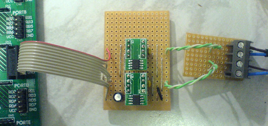
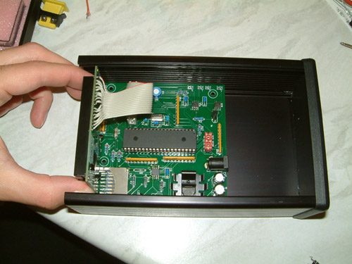
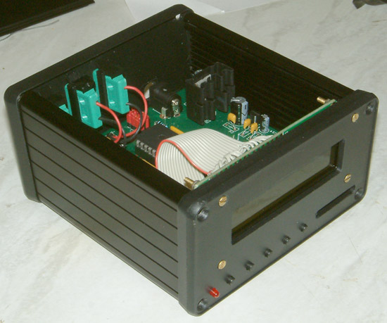
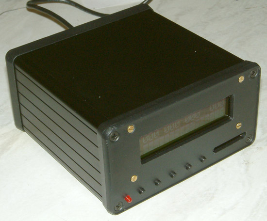
The unit that i have developed
here allows the user to monitor and record three temps from k-type thermocouples, this allows you to measure ambient, intercooler inlet and intercooler outlet temperatures otherwise known as ACT (air charge temp). The air charge temp is important on forced induction cars due to the increase in temps from the compression of the intake air from a supercharger or turbocharger. This is especially important on modified engines with larger turbos or pulley modifications for superchargers. Notwithstanding the recording and monitoring before and after installing aftermarket intercoolers, ducting, water injection and the installation of chargecooling. Monitoring the ACT allows you to see if a modification has had a positive or negative effect on the temperature of your intake.
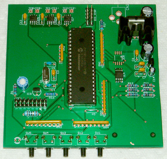
A kit consisting of PCB, parts
list, schematic and pre-programmed micro controller will be available for
you to build if your interested in this
please email me through my contact page.
The project was written in MikroBasic
with an EasyPIC4
Development board and features over 2500 lines of mikroBasic code.
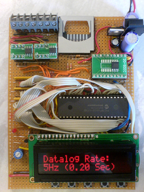
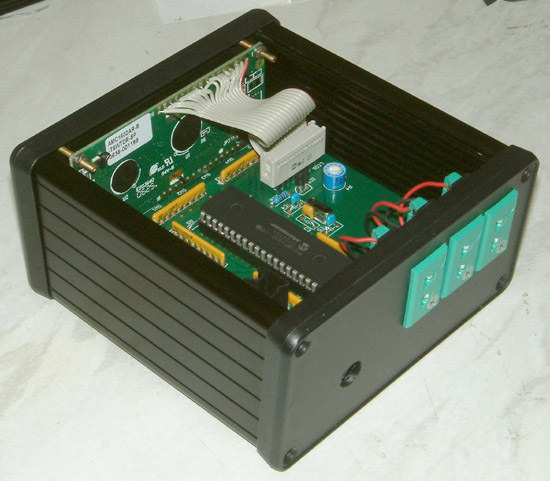
32mhz CPU + 64Kbytes non-volatile RAM
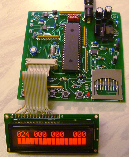
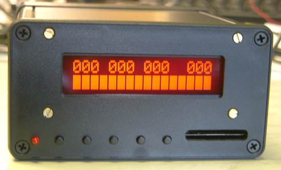
16x2 red-on-black Backlit LCD
Probes: 3 K-Type Thermocouples (Ambient, Inlet & Outlet)
Real-time display of all temps with differential modes
Viewing and Data logging Rates: 0.20s, 0.25s, 0.5s & 1.0s
Logging resolution: 10bit / 0.25 deg C steps
Viewing resolution: 1 deg C with 1/4 degrees shown as mini-bar graph on
each input and differential temp.
1/2 screen, 80 segment real-time bar graph showing % differential ratio
between ambient/inlet, ambient/outlet or inlet/outlet
Max temp display for each probe and max differential temp
Selectable 2, 4 & 8 sample moving average for noise reduction
Working temps: Display Unit: 0 to +50C, Probes: 0 to + 999.75C
Output files open in Excel without adjustment
Auto start feature to automatically start recording when a probe is above
or below a set temperature.
Logging times:
5Hz (0.20 sec): 43 min, 40 secs
4Hz (0.25 sec): 54 min, 36 secs
2Hz (0.50 sec): 109 min, 12 secs
1Hz (1.00 sec): 218 min, 24 secs
Typical output of data from
Excel (data sampled at 5HZ, 0.25 DegC resolution with 4X averaging, all
temps in DegC).
Driving on road with some long
acceleration points, stock engine.
Driving at Anglesey Circuit, big
pulley, Toms style air scoop. (data sampled at 5HZ, 0.25 DegC resolution with 4X averaging, all
temps in DegC)
|