|
This page is dedicated to my Atari TT030
computers, purchased in the early 1990s (my early spec machine) and my 2nd
one in 2009 (my late spec machine)
Sections
Specification
TT-RAM
Clock Battery
Operating System
Video Display
Hard Disk / Solid State Disk
Power Supply
Keyboard
UltraSatan Disk
Links
Specification
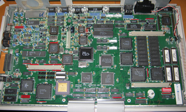
Early Spec TT030 (Backup Machine)
CPU: Motorola 68030 & 68882 @ 32Mhz
with 16Mhz System Bus.
RAM: 4Mb ST-RAM & 4Mb TT-RAM
HDD: 320Mb 3.5" Hard Disk
Video: Standard
Operating System: TOS 3.06UK
Networking: None
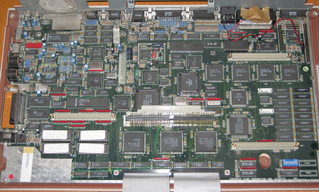
Late Spec TT030 (Main Machine)
CPU: Motorola 68030 & 68882 @ 32Mhz
with 16Mhz System Bus.
RAM: 4Mb ST-RAM & 64Mb TT-RAM (Catch Computer MegTT)
HDD: 2Gb SanDisk Extreme III (TOS) or 4Gb SanDisk Ultra II (EasyMINT)
Compact Flash Cards.
Video: TKR CrazyDots II VME card (ET-4000 with 1Mb) using NVDI
4.11
Operating System: TOS 3.06UK (original single-tasking ROM system)
or EasyMINT
Networking: EtherNEC
External Network
Benchmarks
Below shows GemBench benchmark of my
main machine vs a standard Atari STFM without NVDI
NemBench benchmark of my main machine vs a standard Atari Falcon030
NemBench v2.1 - precision CPU/FPU profiler.

Integer multiply (16bit) -> 1.226 Mips (~200%)
Integer divide (16bit) -> 0.731 Mips (~202%)
Linear (stalled) integer -> 16.094 Mips (~202%)
Interleaved (piped) integer -> 16.094 Mips (~202%)

Float multiply (64bit) -> 0.541 MegaFlops (~204%)
Float divide (64bit) -> 0.351 MegaFlops (~203%)
Linear (stalled) float -> 1.006 MegaFlops (~188%)
Interleaved (piped) float -> 1.003 MegaFlops (~188%)

16bit read (100% hit) -> 15.873 MByte/sec (~202%)
16bit write (100% hit) -> 8.169 MByte/sec (~135%)
32bit read (100% hit) -> 31.746 MByte/sec (~202%)
32bit write (100% hit) -> 16.339 MByte/sec (~245%)

Linear 32bit read (ST-Ram) -> 7.867 MByte/sec (~148%)
Linear 32bit write (ST-Ram) -> 7.867 MByte/sec (~121%)
Linear 32bit copy (ST-Ram) -> 3.947 MByte/sec (~122%)

Linear 32bit read (FastRAM) -> 12.615 MByte/sec (~237%)
Linear 32bit write (FastRAM) -> 15.772 MByte/sec (~244%)
Linear 32bit copy (FastRAM) -> 7.881 MByte/sec (~244%)
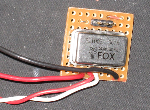
68882 FPU Overclock / Speeder
The FPU in the TT is normally clocked
at 32Mhz, however due to the design of the TT it is simple to
overclock the FPU using a crystal oscillator (see: Atari
TT030 Headquarter for more information).
32Mhz Standard Results:
Float multiply (64bit) -> 0.541 MegaFlops (~204%)
Float divide (64bit) -> 0.351 MegaFlops (~203%)
Linear (stalled) float -> 1.006 MegaFlops (~188%)
Interleaved (piped) float -> 1.003 MegaFlops (~188%)
40Mhz Overclock Results:
Float multiply (64bit) -> 0.672 MegaFlops (~253%)
Float divide (64bit) -> 0.436 MegaFlops (~252%)
Linear (stalled) float -> 1.148 MegaFlops (~215%)
Interleaved (piped) float -> 1.147 MegaFlops (~215%)
Catch Computer MegTT
TT-RAM Board
This 3rd party ram board allows upto 8
16Mb 30pin SIMMs for a total of 128Mb ram. I have 4 16Mb 60ns Fast Page
Mode 30-Pin SIMMs in mine
for 64Mb. Instructions for the MegTT board in German and English can be downloaded
here. The SIMMs were purchased new in 2009 from ebay. TT-RAM is much
faster than ST-RAM because it does not have to share it's use with the
older 'ST' architecture components.
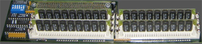
Catch Computer MegTT FastRAM Expansion
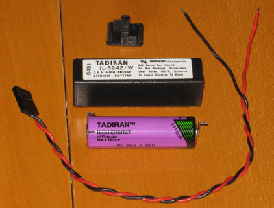
Clock Battery
The Clock battery in the
TT030 is a 3.6v AA Lithium Thionyl Chloride,
if yours is flat you can pop open the case and replace
the cell.
Operating Systems
My TT030 has TOS 3.06 UK loaded into ROM.
Generally i have two CF cards one of which is dedicated to the TOS
operating system and the other is dedicated to MiNT. MiNT or MultiTOS as
it was known under the Atari brand was a full
multitasking operating system that was released by Atari just before
their computing division was essentially abandoned. It and other parts
of the OS have been since refined by open source projects to form the
EasyMiNT and XaAES combination. It's in this area that generally any new
development of Atari software occurs.
Video
Although the standard TT030 has better
video ability than the older Atari ST the modes are still pretty limited.
During the 90s i'd purchased a TKR CrazyDots II VME video card. The
original video drivers were replaced with NVDI ET-4000 which greatly accelerates
the video output.
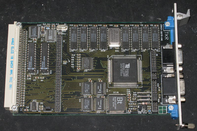
TKR CrazyDots 2 VME (Tseng Labs ET-4000 1Mb)
I have created some video modes for use with my
Samsung 2053BW (20" wide screen monitor) as my original settings
did not produce a good picture. You can download my NVDIVGA.INF
file which contains 640x400, 800x600 & 1024x768 modes in standard
VESA VGA and XGA timings.
Generally i use 1024x768x256. I would
prefer to use 1280x800x256 as it suits my wide screen TFT display but the CrazyDots II card i have does not
quite have enough bandwidth to generate the 85Mhz pixel clock required. I can
display it, but loose about 20 lines off the bottom of the screen.
If like me you found using the VMG-4000
application a bit confusing and difficult to use i've written some tips
here to help you along, once i understood exactly what the settings
meant i could translate them into standard timing terminology.
The horizontal and vertical signals
contain sync information, this sync pulse allows your monitor to sync
itself to the signal so the frames (vertical) and scan lines
(horizontal) data is displayed correctly. The sync appears at the end of
each horizontal or vertical visible data. The timing of these signals
are usually represented in pixels, you can see in the details below
although the 'Visible Area' is 1024x768 the whole signal is 1344x806.
The extra 'pixels' are not displayed but contain the sync pulse.
When the visible part of the signal has
finished the Front Porch starts, then the Sync Pulse itself starts and
then finally the Back Porch. The number of pixels shown next to the
timing below indicates the time period each part should last
|
Horizontal (Scan line)
|
Pixels
|
Time [�s]
|
|
Visible area
|
1024
|
15.753846153846
|
|
Front porch
|
24
|
0.36923076923077
|
|
Sync pulse
|
136
|
2.0923076923077
|
|
Back porch
|
160
|
2.4615384615385
|
|
Whole line
|
1344
|
20.676923076923
|
|
|
Vertical (Frame)
|
Lines
|
Time [ms]
|
|
Visible area
|
768
|
15.879876923077
|
|
Front porch
|
3
|
0.062030769230769
|
|
Sync pulse
|
6
|
0.12406153846154
|
|
Back porch
|
29
|
0.59963076923077
|
|
Whole frame
|
806
|
16.6656
|
|
|
Refresh
Rate: 60HZ, Pixel Clock: 65MHZ
|
Lets now look at VMG-4000:
VMG doesn't express the timing in the same
way as you would normally see, lets do a quick translation.
Auflosung = Visible Area
Schwarzsch = 'Black Area', this is the length of the whole sync
Impulsstart = Starting point of the Sync Pulse
Impulslange = Length of Sync Pulse
Pixel / Zeile dopplet = Pixel or Line Doubling
Sync Negativ = Polarity of sync,
Ok, now to convert the timings shown above:
Auflosung is easy as it's simply the
resolution we want to display, in this case 1024 horizontal and 768
vertical
Schwarzsch is the total length of the sync including front and back
porch. So horizontal: 24+136+160 = 320 and vertical: 3+6+29 = 38
Impulsstart is the start point of the sync pulse. Which is the
visible area + front porch. So horizontal: 1024+24 = 1048 and
vertical: 768+3 = 771
Impulslange is the length of the sync pulse, so horizontal = 136
and vertical = 6
You should also pay attention to the
polarity of the sync, different resolutions have these positive/negative
in different combinations. Though on some monitors it's best just to try
all combinations to get the best picture.
For a complete list of most resolutions see
here.
Hard Disk / SSD
Having used CF cards in other projects (CF
based Rio Karma) i wanted to use some form of flash memory. CF cards
are essentially IDE devices so i needed a way to convert SCSI into IDE,
after a short search on ebay i found the I-O Data Device IDSC21-E
converter board. This small board is designed to allow IDE CD-ROM drives
easy connection to SCSI enabled machines.
The I-O Data IDSC21-E card arrived to me
with firmware v1.01 and caused no end of problems. I did find some
firmware updates for it and after much swearing i managed to flash the
new firmware in which improved things no end. The v1.27 firmware i used
can be downloaded here, note that
it does require you to boot into DOS on a PC with SCSI support. You are also
required to power cycle the card during the update, so using a
power supply that you can turn on/off is an advantage. The update
process goes like this: enable JP8, boot into dos and start the update,
when told you should power off the card, remove the JP8 jumper and then
power back on again and the update will finish. My ISDC21 jumper settings are as follows:
JP1:OFF, JP2:OFF, JP3:OFF, JP4:OFF, JP5:ON, JP6:OFF, JP7:ON, JP8:OFF,
JP9:OFF, CN5A:OFF, CN5B:ON, CN5C:ON.
After the i had everything working the
IDSC21 and the Compact Flash adaptor where mounted into the standard TT
hard disk tray, the standard drive access LED was removed and replaced
with the one from the CF adaptor card as you can see in the pictures
below. Read/Write speed is approx 1.8Mbyte/sec.
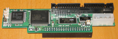
I-O Data Device IDSC21-E
|
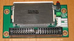
IDE to Compact Flash
|
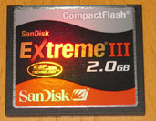
2Gb SanDisk Compact Flash
|
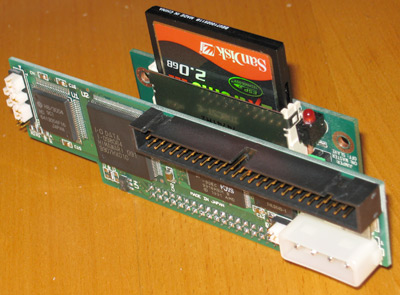
All three assembled together.
|
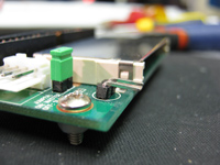
LED from the CF adaptor removed
and replaced with a 2 pin header
|
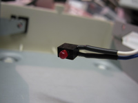
The LED relocated for the
external access light.
|
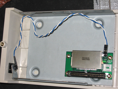
This was then located in the TT's hard disk tray.
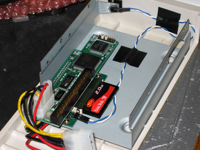
Then finally put together. Cheap SCSI SSD for Atari.
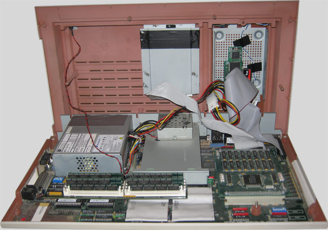
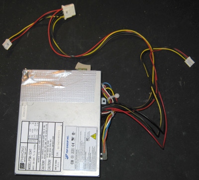
Power Supply
Due to a number of reasons, one being
unreliability (random crashes and memory errors) and the internal PSU
being very noisy i have started to look into replacing the internal
power supply with a new one. My first test was to use a standard ATX
450W PSU. I have chosen a small ATX Flex type PSU as these are
small enough to fit (with some modification) into the normal location
for the power supply, but will also be quieter and have a higher rating
than the 65W OEM unit. I used a FSP Group model FSP250-50GUB.
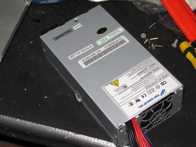
ATX Flex PSU, FSP brand 250Watt
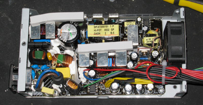
Inside the Flex
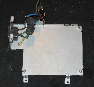
The Atari / PhiHong 65Watt PSU case with the old PSU board removed
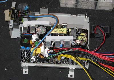
Flex PSU board fitted to old case.
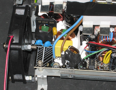
The Flex PCB protruded slightly into the stock fan area. So the standard
fan
was removed and replaced with a slimmer one and fitted with spacers (M4
nuts!). The old fan probably needed
replacing after 19 years anyway. The 40mm fan from the new PSU was removed.
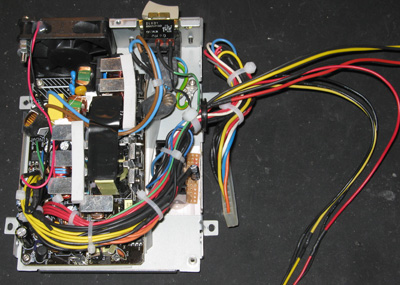
Complete, at this stage i re-wired the mains input to be on permanently and
use the power switch to control the PWR_ON function of the PSU.
Redundant wires chopped short, insulated and tidied up. Note the small piece of
strip board at the side of the chassis, this is a 7905 -5v regulator
attached to a small heat sink. The Flex PSU does not provide a -5v
output which is needed in the TT. I used the -12v output via the volt
regulator to generate the -5v. The motherboard connector was removed
from the old PSU and spliced onto the output wires so it plugs in OEM
style.
Ready to install! With obligatory gaffer tape to seal the air gap around
the smaller fan.
Keyboard
A new keyboard was purchased from 16/32
systems because i had some faulty keys on my original one. I was
only able to buy a Swedish keyboard but thankfully the regional coding
is in the TOS operating system and not in the keyboard so i only need to
swap the key tops from my broken keyboard to the new one.
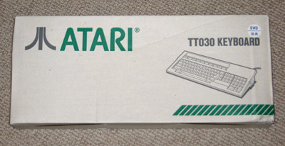
In the box for over 15 years!
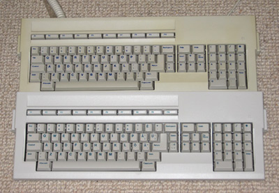
Old keyboard (yellowed) and the new one.
Repairing Faulty TT or MegaSTE keyboards:
This is a common fault on TT and MegaSTE
keyboards, part of the membrane circuit is worn away after long periods
of time, it's a simlpe but careful repair.
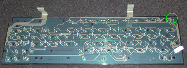
First remove the keyboard and the metal
backing plate to remove the membrane. The most common place is located
around the F1 key.
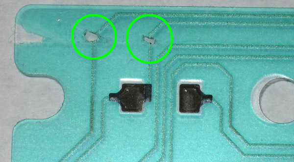
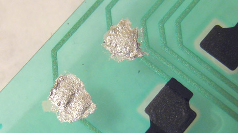
Locate the broken tracks and repair with
conductive paint.
UltraSatan
SD card adaptor for Atari computers, on
order & waiting for delivery - more to come.
Links - Other great general Atari or
TT030 specific sites.
phsw.atari.org
Zogging Hell
www.atari-forum.com
EasyMiNT
Home
|